The Vacuum System
Our vacuum target
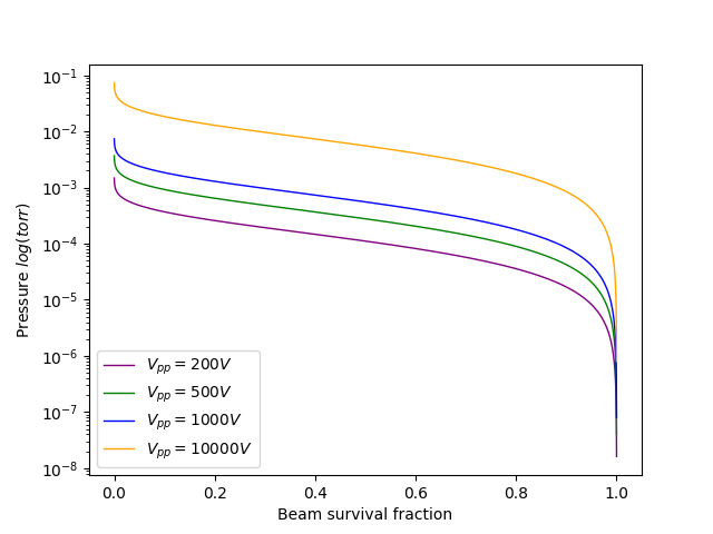
We determined our vacuum target through a statistical beam-loss analysis. Ideally, every proton that enters the dees through the ion source will collide with the target at exactly the target energy. Unfortunately, such aspirations are unreasonable because of the impossibility of removing all of the atmospheric gas (and gas we introduce through the ion source) from the chamber. Beam particles are doomed to scatter off these residual gas molecules and we can assume that most of these scattering events fatally eject protons from the beam. By analyzing these scattering events statistically we can determine the fraction of the beam that we expect to lose at a given chamber pressure and acceleration voltage. That plot is shown below, and the result is a vacuum target somewhere between 10-4 and 10-5 torr.
About the vacuum system [now out of date, 11/12/2024]
Recent updates: 05/2024
We have recently switched from using a cryosorption pump to an oil diffusion pump for finishing. The sorption pump was simply too expensive to operate, despite its simplicity and low overhead cost. Each test required a substantial quantity of liquid nitrogen which had to be purchased expressly for the purpose of the test at hand because we are unable to store it for long periods on-site. It is frequently months between tests and we would like to be able to iterate without purchasing many liters of liquid nitrogen each occasion we test.
We will achieve our vacuum target using a combination of pumps. We have a Varian SD-90 rotary vane pump for roughing and a diffusion pump (of unknown model) for finishing.
Our rotary vane pump was acquired secondhand and is in need of a thorough cleanup but we hope it will be able to reach 10-3 torr.
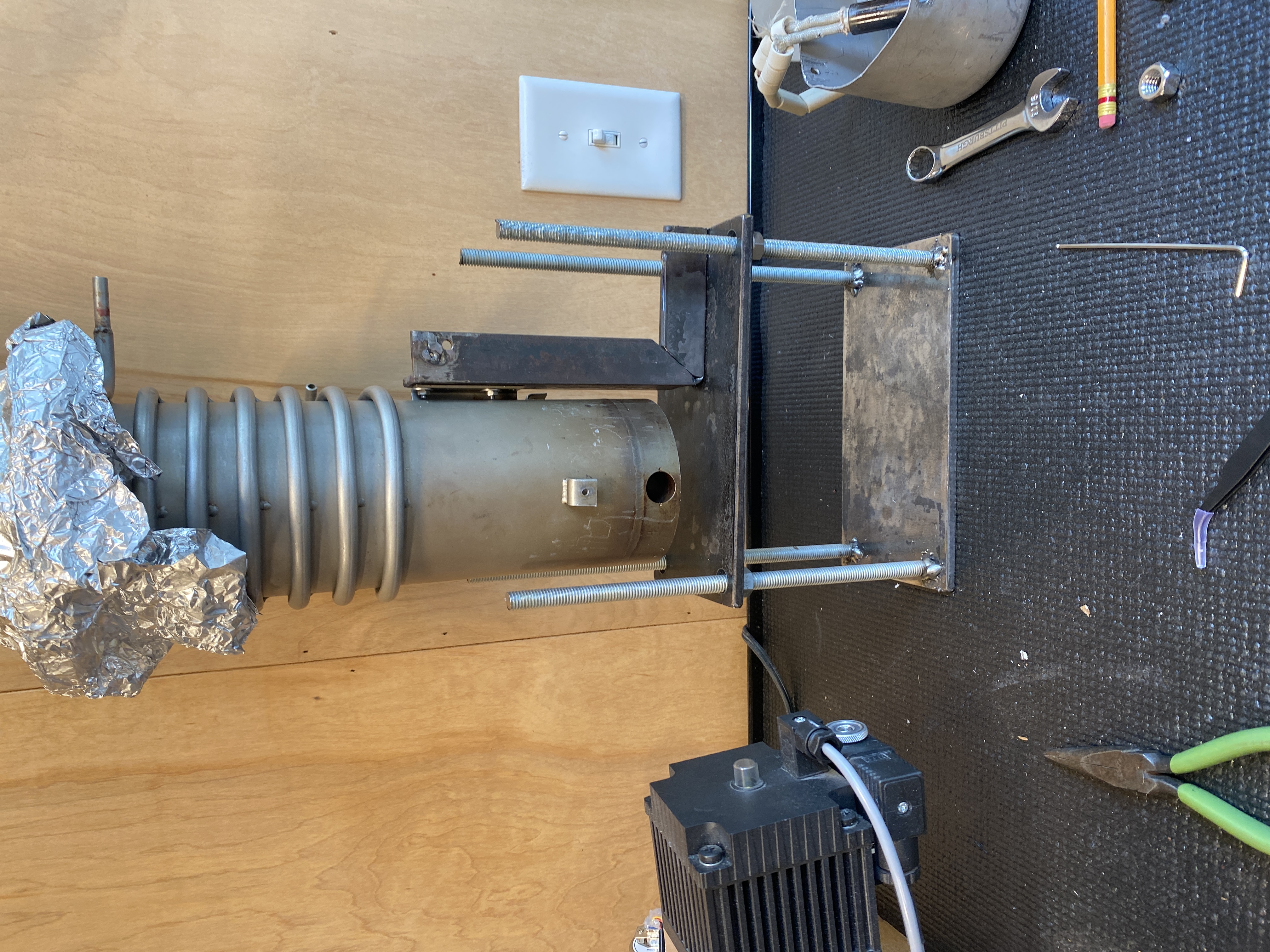

Historical design: cryosorption
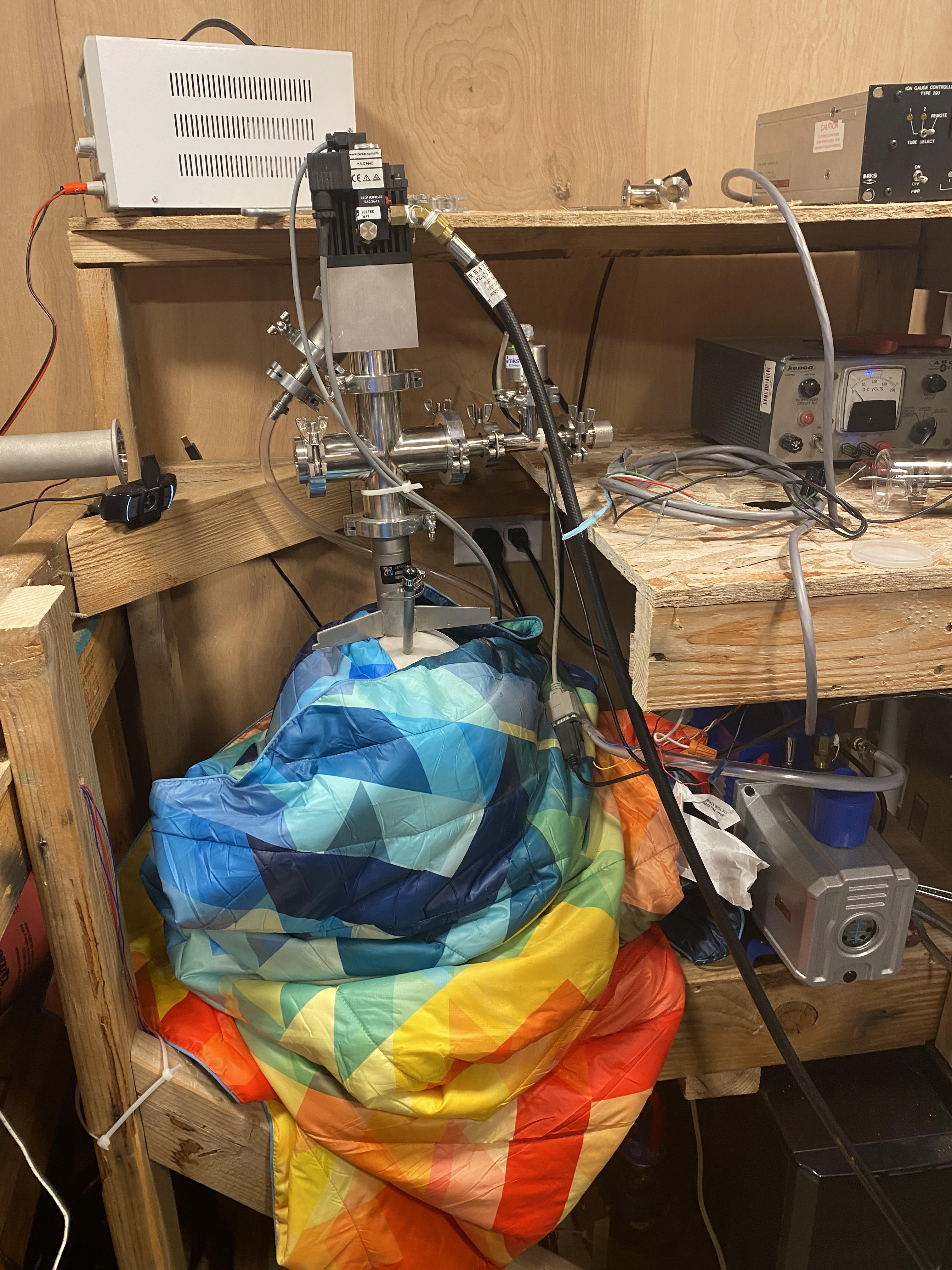
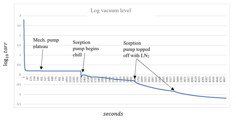
Our vacuum manifold is designed such that the mechanical pumps can be isolated from the vacuum chamber once they have hit their minimum pressure, allowing our cryosorption pump to pull out much of the remaining gas. Cryosorption pumps (or just “sorption” pumps) are designed to be cooled down to very low temperatures (below 77K, the boiling point of liquid nitrogen) so that residual gas can condense on a high surface area material in their interior. Our pump is filled with zeolite pellets, a high surface area ceramic. A photo of the sorption pump in its nitrogen bath is below:
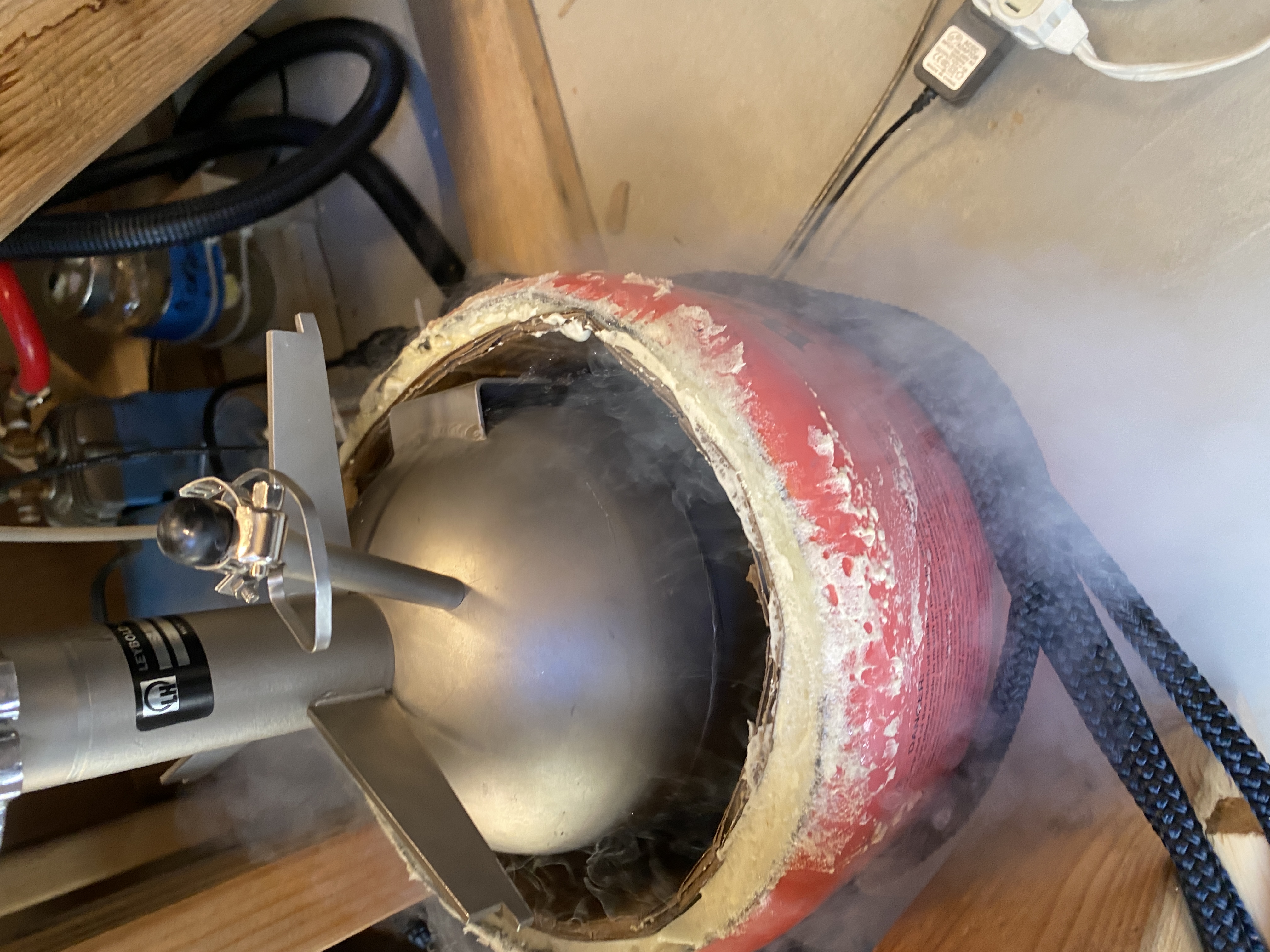
The sorption pump during our most recent cryogenic test. The blanket is for extra insulation.
A normal vacuum pumpdown profile (normal, except for the mediocre final vacuum).
Design considerations
Budget
We designed our vacuum system on a stringent budget, so we are using primarily KF type flanges, the more affordable counterpart to CF flanges with copper gaskets. KF flanges use O-rings rather than costly single use copper gaskets, and can be interchanged readily. KF flanges, however, are leaky in comparison to the CF type and – although rated to 10-7 torr – we are pushing the limits of their reasonable capability (and our sanity). The Shed is far from a cleanroom environment and we are constantly fighting entropy, trying to keep dust and debris off our o-rings and sealing surfaces.
Geometry
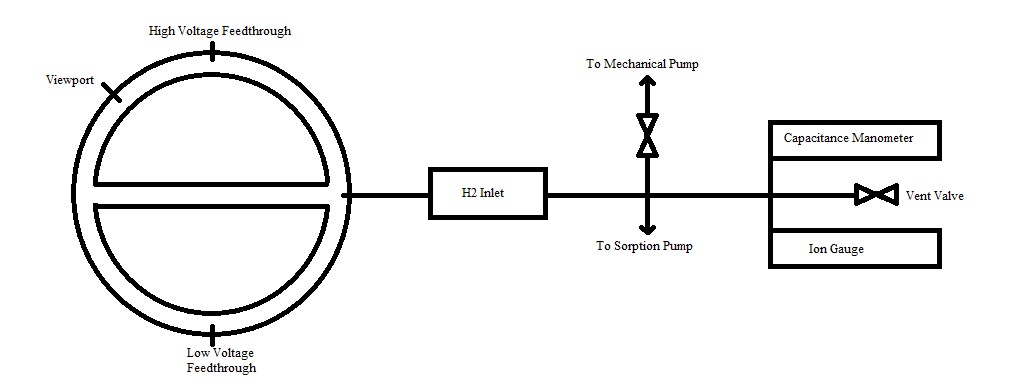
The performance of high and ultrahigh vacuum systems is somewhat dependent on their geometry. This is due to the extremely low gas densities encountered in the high and ultrahigh vacuum regimes; the mean free path is large enough that we are essentially dealing with billiard balls (gas molecules) rather than a continuous fluid. The relevant interactions of gas molecules become primarily those with the walls of the vacuum system. Thus, it is important to design the system so that it directs gas into the vacuum pump inlets. Ideally, we would have the chamber directly open to the inlet of a cryosorption pump or a turbomolecular pump (a very nice but extremely expensive form of vacuum pump) so that there is a direct path from the median plane (where we don’t want any gas) to the pump (where we trap or expel the gas). We have two large magnets and a host of other equipment in this area, however, so we must cope with a slightly longer escape path for trapped gasses.
Below is a rough layout of the majority of the vacuum system.
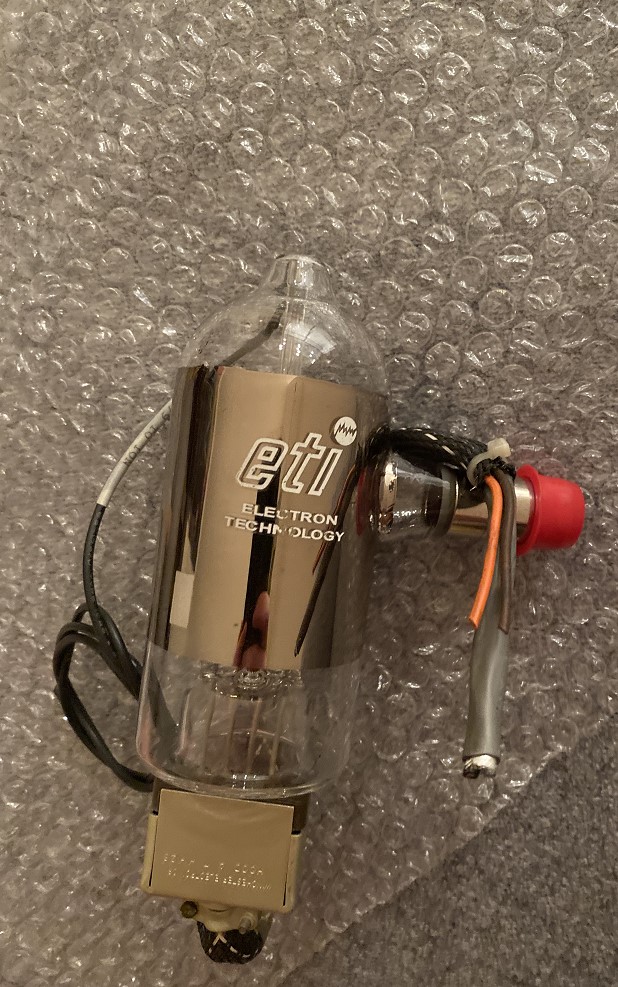
Below is a photo of the ion gauge.
Vacuum issues and setbacks
Although we have reached vacuums in the 10-3 torr range, we have been unable to test the system below that. We recently replaced a leaky bellows isolation valve (it had a cracked fold) with a pneumatic O-ring sealed valve to eliminate that leak and reduce the gas load on the pumps. In the span of time between the last cryogenic test and installing the new valve the uninsulated shed hit temperatures of -25˚C. Water vapor in the air condensed and froze onto every surface, coating the inside of the vacuum system in a thin layer of ice. This introduced a lot of water into our otherwise clean vacuum system and contaminated the oil in our mechanical pump. Subsequent tests show that the outgassing is so extreme we cannot pull the system below 0.5 torr with the mechanical pump and 4.42 · 10 -2 torr with the sorption pump. Thus, we need to replace the vacuum pump oil and bake out the whole system. This is in progress.
The vacuum profile during pumpdown after the freeze.
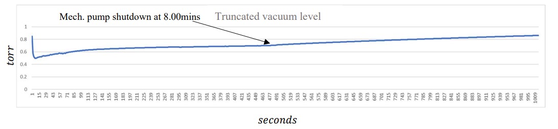
The above photo shows some of the outgassing problem. As this data was collected, the vacuum pump oil was visibily bubling (far above its vapor pressure), indicating a large amount of disolved gass or emulsified water.