The Magnets
“The best unit for quantifying our fire risk is the Tesla” -Reed Michael
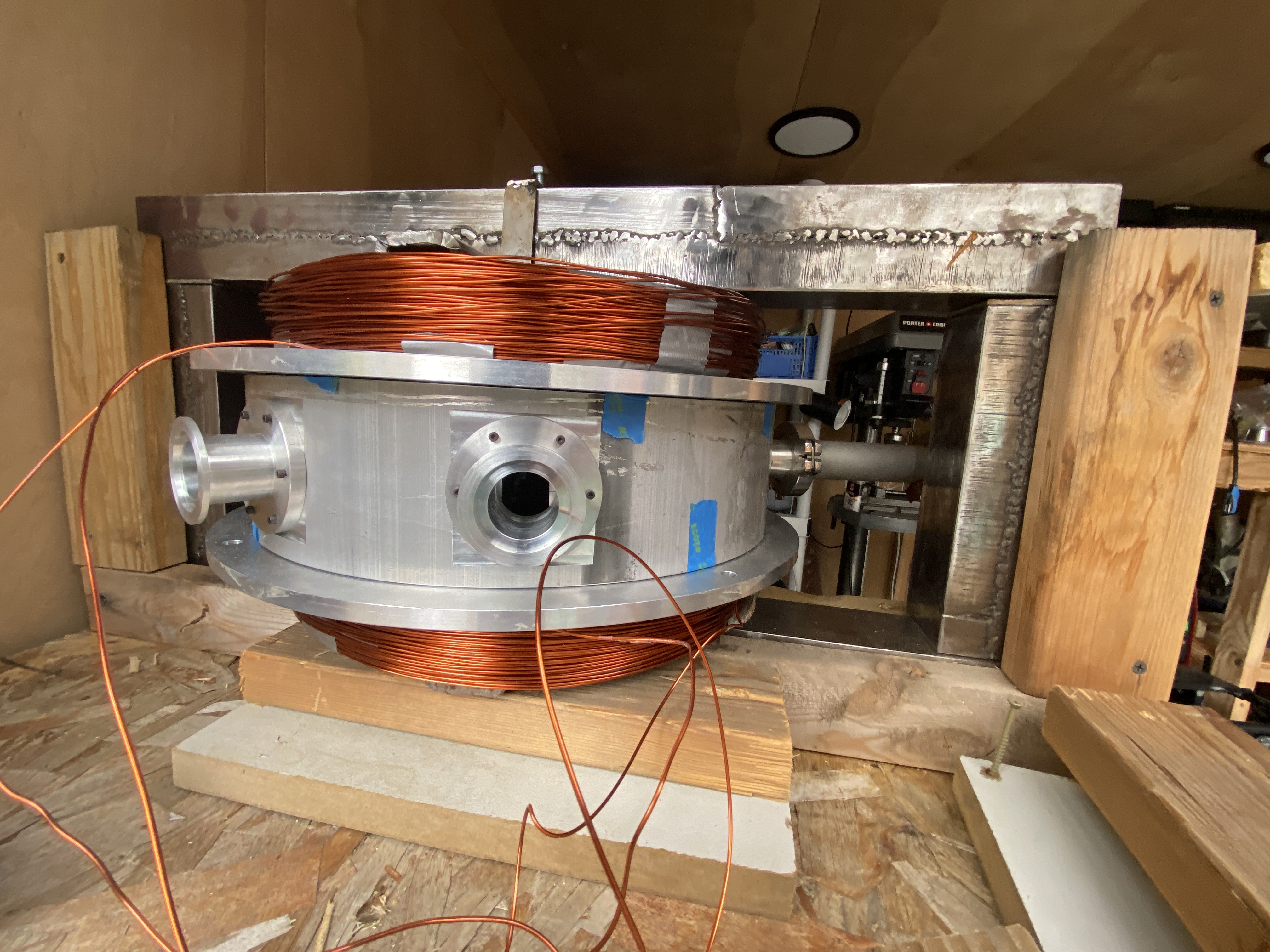
The magnets generate the magnetic field to contain our precious protons as they are tugged on by the electric field of the dees. They represent one of the three major cyclotron subsystems and present their own host of engineering challenges. Our magnets are designed to run up to 0.3T, and they are by no means efficient at doing this. The magnets heat as we pump high currents (up to 30A) through the coils and we currently don’t have any means of actively cooling them. Thus, we are limited to running them in short pulses. We aim to maximize the field strength while keeping within a safe temperature range. We especially want to minimize the heat absorbed by the vacuum chamber (particularly the large o-rings sealing the top and bottom of the main chamber).
Operating the magnets
The magnets are run using two Variac variable transformers – one for each magnet. The output of each transformer is rectified and fed to the coil. It is very important that we regulate the magnets carefully and that they can be controlled independently – varying the field characteristics in the median plane. As this must be done remotely, we drive the Variacs using stepper motors controlled via an Arduino which is networked to the rest of the system.
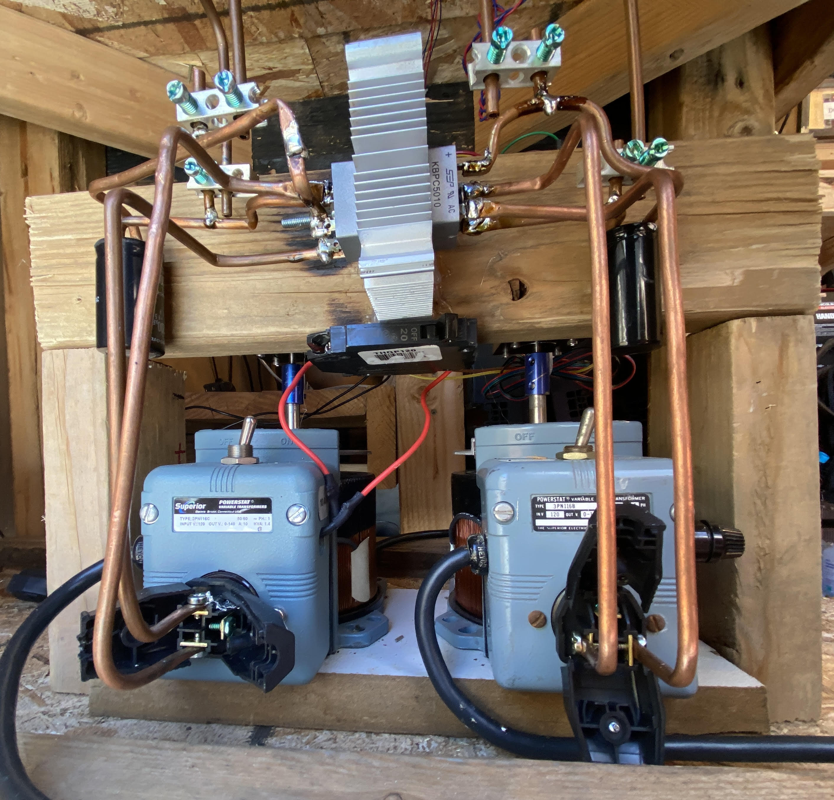
The rectifier circuit uses two independent rectifier modules and smoothing capacitors. All connections were made with .25” copper tube to minimize the voltage drop between the variacs and magnet coils.
We have attached thermocouples to each magnet which give us the temperature of each magnet individually and trigger an automatic shutoff if either magnet begins to overheat.
The yoke
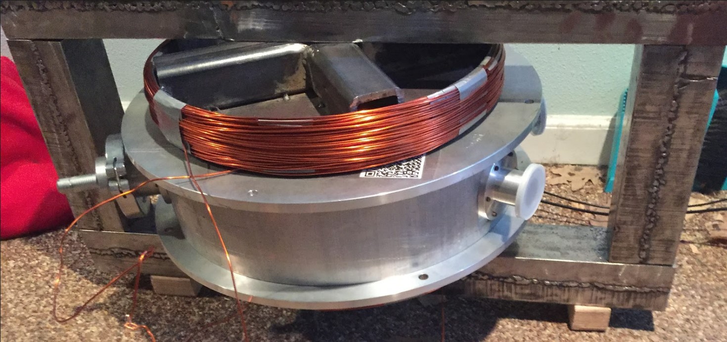
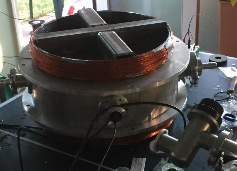
The solid steel yoke doubles the efficiency of our magnets, greatly reducing the current we must supply. Furthermore, the yoke acts as a large heatsink that helps to cool the magnet coils. It is a simple structure: a rectangular arrangement of solid steel bars – which have high magnetic permeability. The coils themselves are each wound around a steel frame which further improves magnet performance. This structure, however, is not solid – as making it solid was prohibitively expensive. Due to budgetary constraints (and the generosity of a friend) we constructed the main structure of the yoke from discarded elevator weights. These were cut to size and then welded together. In total, the yoke and magnets weigh a bit over 400lbs.
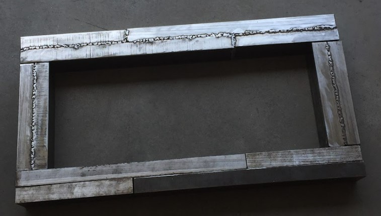 Please pardon the welds – I am a horrible welder, but I am learning! -Reed Michael
Characterization
One of the components of our magnet test campaign is mapping the field shape in the median plane. Via these measurements we hope to check that the magnets are properly wound and aligned and quantify the effect of the four-fold symmetric magnet supports. We have completed a prototype “mapper” and run some preliminary maps.
The “mapper” prototype
The mapper prototype consists of an array of six hall effect sensors spaced evenly along an arm which can rotate around the median plane. The sensors are read out by an Arduino and the data is fed into python for analysis. The prototype is shown below, along with a qualitative plot of the first results.
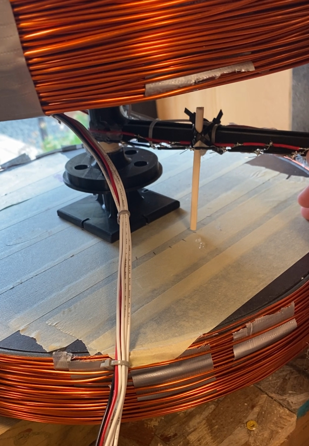
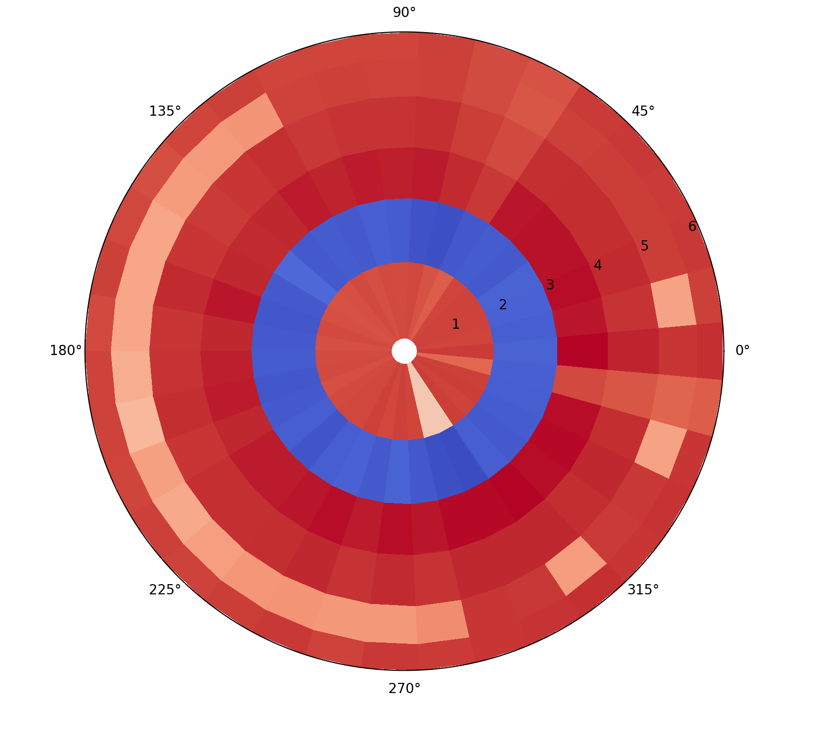
(pardon the lack of units, this test was primarily to recover qualitative information about the performance of the mapper and not to accurately map the magnets)
It is clear that some changes must be made… Firstly, the resolution is unacceptably low. This is limited by the fact that the prototype was manually rotated around the median plane, aligning it with marks made on the magnet poles. Thus, to complete the map in a reasonable amount of time we could only record 10 degree intervals (remember, the magnets must ramp down in between each measurement, making this process extremely time consuming). Secondly, the multi-sensor detector is terribly temperamental. As is clear from the above map, sensor 2 is dead – an unfortunate consequence of cheap sensors.
The next prototype
We are currently designing another prototype which will include the following improvements:
-
Automated movement. We will control the movement of the sensor via a pully drive (with the magnetic components outside of the test area) so that we can reliably gather higher resolution data with lower positional uncertainties.
-
Single sensor design. We will use a single more reliable hall effect sensor, which will automatically scan the whole area. This allows us to avoid sensor failures and has the additional benefit that we can be sure each pixel of the measurement has the same response profile (this was an assumption in the prior case, but was not strictly true because the measurements were made with different sensors)
-
Better alignment. The prior prototype was difficult to align with the magnet poles. This will be fixed with a more robust mounting system that effectively wedges itself between both poles of the magnets so that there is less net torque on the center post.