The Cyclotron Project
Update: 11/12/2024
As of 11/12/2024 this website is sorely out of date. We have made significant progress on the vacuum system and ion source and are in the process of validating both of the new systems. We are also working on producing an extensive set of documentation regarding the detailed design of the cyclotron and proper SOPs. We’ve also adjusted our target specs to conform to the systems we have actually constructed and validated (for example, we’ve revised our target beam energy to 60KeV due to incidental radiation concerns).
More information will come to this website soon.
Regards,
The Cyclotron Team
What is the goal?
Although we have a number of experiments in mind, our threshold goal is to accelerate protons to energies of 60KeV. Although this pales in comparison to the beam energy of even our most primordial research cyclotrons this is both safe and attainable on an amateur level.

FAQs:
What is a cyclotron?
A cyclotron is a form of particle accelerator which leverages the Lorentz force exerted on charged particles moving in a magnetic field. This allows otherwise long beam-lines to be ‘wound’ into small volumes. As a result, cyclotrons are often very compact compared to linear accelerators achieving similar energies. Our cyclotron has a target energy of 1.1MeV (mega electron-volts) and fits in a garden shed (hereafter referred to as The Shed)! The space in which the particles circulate is a cylindrical chamber only 16” in diameter and 4” tall.
It looks complicated, what does everything do?
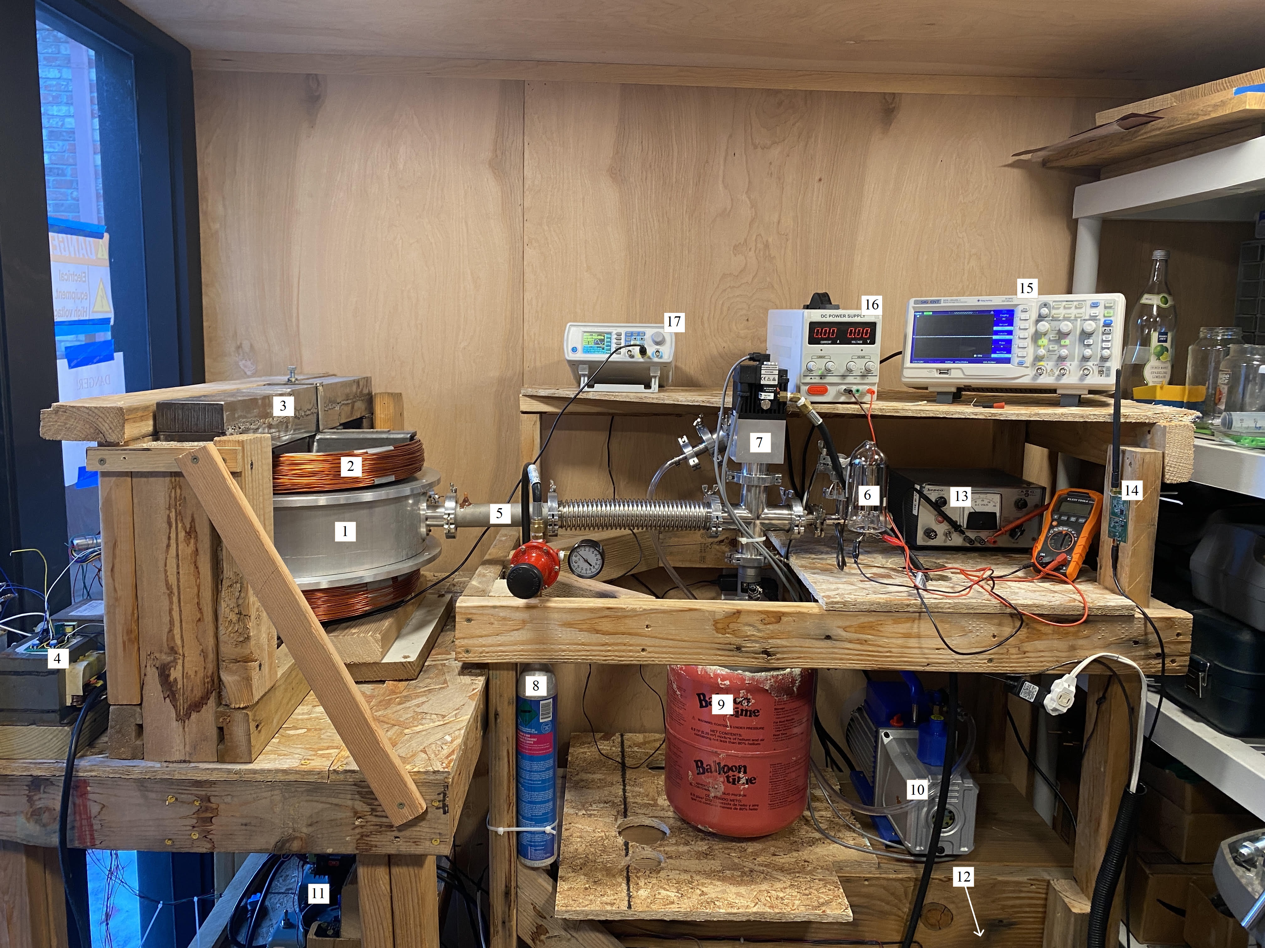
1) Dee chamber. This is where the dees reside – the protons circulate inside the dees.
2) Magnet. This is one of our two magnets (the other is under the dee chamber), it helps constrain the protons as they accelerate.
3) Magnetic yoke. This creates a magnetic circuit between the two magnets, improving their efficiency.
4) Oscillator amplifier. This amplifies the signal from the function generator (17) into a high voltage driving signal for the dees.
5) H2 inlet. This is where we inject hydrogen into the ion source.
6) Ion gauge. This is one of our two vacuum gauges – it allows us to accurately measure very low pressures.
7) Pneumatic valve (for isolating mechanical pump). This allows us to remove the mechanical pump (which is, by high vacuum standards, very leaky) from the system.
8) CO2 source for pneumatic valve. This is the gas cylinder which supplies the pressure to actuate the pneumatic valve (7). This photo is slightly outdated, we now use a large high pressure Argon+CO2 cylinder to supply the valve, rather than a small CO2 cylinder.
9) Sorption pump and liquid nitrogen reservoir. The outer pink drum is the LN2 reservoir (soon to be replaced), and the inner silver cylinder is our sorption pump. This allows us to attain vacuums below ~10-1 torr.
10) Mechanical pump. This is our roughing pump. At the present time, this takes the system from atmosphere to ~1 torr.
11) Magnet Variacs and drivers. These are two variable transformers coupled to stepper motors, allowing us to remotely control the power of the two magnets.
12) Main control server. This is the “brain” of the cyclotron. It regulates all automatic functions and transmits and receives relevant data.
13) High voltage power supply for ion Gauge. This would supply the filament to gate voltage for our ion gauge (6). This photo is slightly outdated, and this component (as well as 16) has been replaced by a dedicated ion gauge controller.
14) Network card for server. This connects the server (12) to the world.
15) Oscilloscope. A tool used for general electronics testing.
16) Low voltage DC power supply. This is used for general electronics testing.
17) Computer controlled function generator for oscillator. Used to generate the waveform driving the dees.
Why are you building one?
Why not build a particle accelerator in your backyard? The project began in school when a teacher asked us if we wanted to try building a cyclotron. They were clearly ignorant to how much effort this would take, and we were too, but we started the project nonetheless. We each possessed a useful subset of the skills needed, and we took this as an opportunity to develop those as well as build off one another’s core competencies.
What is left to do?
We currently have all subsystems running at some level or another, but we are yet to fully integrate all systems. The vacuum system needs to undergo a full bakeout and a third cryogenic test before we can declare it complete. We recently fixed several leaks and replaced one of our isolation valves. Those changes need further testing in concert with the sorption pump. Furthermore, The (uninsulated) Shed recently hit temperatures of -25C, causing a layer of ice to form inside the vacuum system. This introduced a large amount of water into our mechanical vacuum pump oil. We have since been able to pull the vacuum system down to 4.42 · 10-2 torr, but are struggling with outgassing.
The magnets are functional to ~.1T, and we have recently built improved rectifiers to run them at higher field strengths. We must test these further and certify them at much high field strengths for short periods of time. The magnets are a limiting aspect of the system, as they are passively cooled and heat very quickly during operation.
The RF oscillator is complete but needs additional testing at higher amplitudes. Our target peak to peak amplitude is 1.2kV.
Where is this, is it safe?
The setup takes up the left half of Reed Michael’s garden shed, although the “whole” cyclotron essentially inhabits the entirety of The Shed. We designed The Shed, in part, to contain the cyclotron – and it is certainly not your typical garden shed. We have a 12 kilowatt electrical connection divided between two 120V AC circuits and a 240V AC circuit. The Shed is also a Faraday cage, and all of the electrical lines are run underground to minimize RF leakage. Our greatest risk is fire, which is mitigated by accessible fire extinguishers and appropriate thermal control. Everything is controlled via a server running fault tolerant Linux and, of course, we have a mechanical power disconnect. When running, the cyclotron will also be an X-ray source. We have plans to cover the chamber in lead foil, and we have a personal dosimeter and will have additional dosimeters in and outside of The Shed. Everything is controlled from a distance over a redundant wireless link (with mechanical shutoffs).
What are the specs?
Our cyclotron is a small, 1.1MeV proton cyclotron with 14” diameter “dees.” Our magnets produce a field of about 0.3T in the median plane. We have no azimuthal correction, so our energy is relativistically limited. Our vacuum target (not yet met) is 10-5 torr. We use two mechanical pumps and one cryosorption pump to achieve this. A comprehensive overview of all systems is coming to this website soon.